Symbolic Method
Steinmetz Usage
Section titled “Steinmetz Usage”The symbolic method is Steinmetz’s complex-number method for representing alternating-current quantities. It makes magnitude and phase calculable in one expression, allowing resistance and reactance, or conductance and susceptance, to become parts of a structured mathematical object.
In the OCR seed for Alternating Current Phenomena, the symbolic method appears near vector representation, resistance, reactance, impedance, capacity reactance, Kirchhoff’s laws, and power representation. That placement tells us how the method functions: it is not an isolated mathematical trick, but the bridge from sinusoidal waves to usable circuit calculation.
Modern Equivalent
Section titled “Modern Equivalent”Modern electrical engineering teaches this as phasor analysis and complex impedance.
where R is resistance and X is reactance.
Diagrammatic Explanation
Section titled “Diagrammatic Explanation”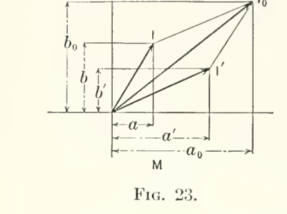
Component addition as the source bridge from vector geometry to symbolic calculation.

Rectangular components, resultant addition, and quarter-period rotation in one source-keyed guide.

Magnitude and phase as a rotating or projected quantity.

Resistance and reactance as rectangular components of a symbolic quantity.
The phasor and symbolic form tool gives a live version of this same geometry by translating magnitude and phase into a + jb.
Why It Matters
Section titled “Why It Matters”The method is one of Steinmetz’s great acts of engineering translation. It turns periodic electrical motion into stable symbolic structure, making AC systems calculable without losing phase.
Reading Warning
Section titled “Reading Warning”Modern notation can make this look too easy. The archive should keep the physical interpretation visible: resistance corresponds to energy dissipation, while reactance corresponds to periodic energy storage and return. The symbolic method compresses those differences into a form that can be added, resolved, and compared.
Research Tasks
Section titled “Research Tasks”- Verify Steinmetz’s original notation for the imaginary unit and symbolic quantities.
- Compare his terminology with modern phasor notation.
- Link symbolic method pages to impedance, admittance, power factor, and harmonics.
- Verify the modern redraw sheet against crop coordinates and full-page scans.
Reader Synthesis
Section titled “Reader Synthesis”What Steinmetz Is Doing Here
The symbolic method is Steinmetz’s engineering translation of alternating quantities into calculable complex form.
The current strongest source route is Theory and Calculation of Alternating Current Phenomena, with 89 candidate hits across 22 sections.
Modern Translation
Modern readers know this as phasor and complex impedance analysis, but Steinmetz’s presentation keeps the geometric origin close to the algebra.
This page currently tracks 316 candidate occurrences across 10 sources and 70 sections.
Mathematical And Visual Route
The core route is rectangular components, the quadrature operator j, impedance, admittance, conductance, susceptance, and phase angle.
Use the math/visual bridge lower on this page to jump into formula families, source visual maps, and candidate figure leads.
Interpretive Boundary
Interpretation should not turn symbolic notation into metaphysics. Its first meaning is mathematical economy for AC engineering.
Layer labels stay active: source claim, modern equivalent, mathematical reconstruction, historical note, and interpretive reading are not interchangeable.
Best Steinmetz Passages To Read First
Section titled “Best Steinmetz Passages To Read First”| Passage | Hits | Location | Open |
|---|---|---|---|
| Chapter 5: Symbolic Method Theory and Calculation of Alternating Current Phenomena | 22 | lines 2760-3266 | read - research review |
| Chapter 30: Quartbr-Fhase System Theory and Calculation of Alternating Current Phenomena | 19 | lines 27501-29124 | read - research review |
| Chapter 32: Quarter-Phase System Theory and Calculation of Alternating Current Phenomena | 19 | lines 25904-27405 | read - research review |
| Chapter 5: Symbolic Method Theory and Calculation of Alternating Current Phenomena | 17 | lines 2322-2773 | read - research review |
Research Position
Section titled “Research Position”- Tracked vocabulary: Symbolic Method, Complex Quantities.
- Concordance: Symbolic Method - Complex Quantities.
- Source discipline: the table above is for reading and navigation; exact quotation still requires scan verification.
- Reader route: read the passage first, then return here for modern translation, mathematical reconstruction, visual routes, and interpretation boundaries.
- Editorial rule: expand this page by promoting scan-checked passages, equations, and diagrams from the linked workbench pages, not by adding unsourced generalizations.
Source Expansion Impact
Section titled “Source Expansion Impact”The symbolic method needs its paper trail, not only later textbook treatment.
Keep the 1897/1900/1916 AC editions visible as the book-development layer while the paper sources remain acquisition targets.
| Source Target | Year | Status | Why It Matters Here |
|---|---|---|---|
| Complex Quantities and Their Use in Electrical Engineering | 1894 | Registered Authority Target | This should become the flagship source for how Steinmetz made alternating-current calculation algebraic, geometric, and teachable. |
| The General Equations of the Electric Circuit | 1908 | Registered Authority Target | This paper bridges steady-state symbolic method, differential equations, and the general circuit theory behind later source books. |
| The General Equations of the Electric Circuit-III | 1919 | Registered Authority Target | The continuation lets the archive show development over time rather than treating general circuit equations as a one-off article. |
Source-Grounded Dossier
Section titled “Source-Grounded Dossier”Generated evidence layer: this dossier is built from the processed concept concordance. Counts and snippets are OCR/PDF-text aids, not final quotations. Verify against scans before making exact claims.
Candidate occurrences tracked for this page.
Sources with at least one hit.
Sections, lectures, chapters, or report divisions to review.
What The Current Corpus Shows
Section titled “What The Current Corpus Shows”Read this concept as a mathematical language page: the important work is not only the formulas, but Steinmetz’s translation between rotating vectors, rectangular components, and symbolic calculation.
The strongest current source concentration is Theory and Calculation of Alternating Current Phenomena with 89 candidate hits across 22 sections.
The dossier is meant to turn a concept page into a reading path: begin with Steinmetz’s source wording, then use the research links only when you need candidate counts, snippets, mathematical reconstruction, historical context, or interpretive layers.
Terms And Aliases Tracked
Section titled “Terms And Aliases Tracked”symbolic, symbolic expression, symbolic method, symbolic representation, complex quantities, complex quantity, imaginary quantities, imaginary quantity
Concordance Records
Section titled “Concordance Records”Symbolic Method - Complex Quantities
Source Distribution
Section titled “Source Distribution”Priority Passages To Read
Section titled “Priority Passages To Read”Chapter 5: Symbolic Method - 22 candidate hits
Source: Theory and Calculation of Alternating Current Phenomena (1916)
Location: lines 2760-3266 - Tracked concepts: Complex Quantities, Symbolic Method
CHAPTER V SYMBOLIC METHOD 25. The graphical method of representing alternating-current phenomena affords the best means for deriving a clear insight into the mutual relation of the different alternating sine waves entering into the problem. For numerical calculation, however, th ...... ram is shown in Fig. 21. Obviously, no exact numerical values can be taken from a parallelogram as flat as OFiFFo, and from the combination of vectors of the relative magnitudes 1 :6 :100. Hence the importance of the graphical method consists not 30 SYMBOLIC METHOD 31 so much in its usefulness for practical calculation as to aid in the simple understa...Chapter 30: Quartbr-Fhase System - 19 candidate hits
Source: Theory and Calculation of Alternating Current Phenomena (1897)
Location: lines 27501-29124 - Tracked concepts: Complex Quantities, Symbolic Method
... .4, a = .1435, a = 8.2°. Impcdarice and Admittance, 283. In complex imaginary quantities, the alternating wave /* '»\ s = £" cos (<^ - cu) is represented by the symbol E - e (cos ci +y sin w) = c^ -\- je^ . By an extension of the meaning of this symbolic ex- pression, the oscillating wave E=^et~^^ cos (<^ - w) can be expressed by the symbol E = e (cos...... . The electromotive force consumed by the inductance L of the circuit, 77 r d I o A- r if f d I Ex = /' - = 2 TT A Z = .V . lit i/<t> ii<t> Hence Ej, = - xit"*'^ {sin (</> - w) + ^ cos (</> - w)} = -- - - -- sin (</> - (u + «)• cos tt Thus, in symbolic expression, ^x = - {- sin (w - a) +ycos (w - a)} dec a COS a = - xi {a -\- J) (cos « + y sin w) dec...Chapter 32: Quarter-Phase System - 19 candidate hits
Source: Theory and Calculation of Alternating Current Phenomena (1900)
Location: lines 25904-27405 - Tracked concepts: Complex Quantities, Symbolic Method
... have A = .4, a = .1435, a = 8.2°. Impedance and Admittance. 312. In complex imaginary quantities, the alternating wave * = e cos (* - ffl) is represented by the symbol E = e (cos w -\-j sin w) = <?x -\-jez . By an extension of the meaning of this symbolic ex- pression, the oscillating wave E = ee~a<t> cos (<f> - w) can be expressed by the symbol E = e...... stance r of the circuit ^ The electromotive force consumed by the inductance L of the circuit, Ef**L-~*iNI&t = *-. dt d<$> d<$> Hence Ex = - xif.~a^> (sin (<J> - fy -\- a cos (<£ - w)} xi(.~a^ . ,. „ , N = sin (^> - w -f- a). COS a Thus, in symbolic expression, £x = - °^-{- sin (w - a) +/ cos (w - a)} dec a COS a = - x i (a -f y ) (cos w + 7 sin a>) d...Chapter 5: Symbolic Method - 17 candidate hits
Source: Theory and Calculation of Alternating Current Phenomena (1900)
Location: lines 2322-2773 - Tracked concepts: Complex Quantities, Symbolic Method
CHAPTER V. SYMBOLIC METHOD. 23. The graphical method of representing alternating, current phenomena by polar coordinates of time affords the best means for deriving a clear insight into the mutual rela- tion of the different alternating sine waves entering into the problem. For n ...... for definition except that it is not an .ordinary number. 27. A wave of equal intensity, and differing in phase from the wave a + jb by 180°, or one-half period, is repre- sented in polar coordinates by a vector of opposite direction, and denoted by the symbolic expression, - a - jb. Or - Multiplying the symbolic expression, a + jb, of a sine wave by...Chapter 5: Symbouc Mbthod - 16 candidate hits
Source: Theory and Calculation of Alternating Current Phenomena (1897)
Location: lines 2744-3229 - Tracked concepts: Complex Quantities, Symbolic Method
... mined analytically by two numerical quanti- ties - the length, Of, or intensity ; and the amplitude, AO/, or phase <o, of the wave, /. Instead of denoting the vector which represents the sine wave in the polar diagram by the polar coordinates. §26] SYMBOLIC METHOD. 35 / and w, we can represent it by its rectangular coordinates, a and b (Fig. 22), wher...... for definition except that it is not an ordinary number. 27. A wave of equal intensity, and differing in phase from the wave a + jb by 180°, or one-half period, is repre- sented in polar coordinates by a vector of opposite direction, and denoted by the symbolic expression, - a - jb. Or - Multiplying the algebraic exprcssiotiy a '\-jby of a sine wave b...Chapter 18: Oscillating Currents - 13 candidate hits
Source: Theory and Calculation of Electric Circuits (1917)
Location: lines 31657-33200 - Tracked concepts: Complex Quantities, Symbolic Method
... e have A = 0.4, a = 0.1435, a = 8.2°. Impedance and Admittance 184. In complex imaginary quantities, the alternating wave, z = e cos (0 - 6)^ is represented by the symbol, fl = e(cos d - j sin ^) = ei - je2» By an extension of the meaning of this symbolic expression, the oscillating wave, JS? = tt"*** cos {<t> - 6), can be expressed by the symbol, JjJ...... e then, the e.m.f. consumed by the resistance, r, of the circuit, Er = rl dec a. The e.m.f. consumed due to the inductance, L, of the circuit, n T dl rk TT dl dl Hence E^ = - a;i€-"*{sin (0 - ^) + a cos (0 - ^)} = sm (0 - ^ + a). cos a Thus, in symbolic expression, jFx = I - sin {B - a) - j cos (^ - a) } dec a cos a / ^ \ /I = - xtXa - j) (cos ^ - j s...Reading Layers To Build Out
Section titled “Reading Layers To Build Out”| Layer | What to add next |
|---|---|
| Steinmetz wording | Pull exact source passages only after scan verification; keep OCR text labeled until then. |
| Modern engineering reading | Translate the source usage into present electrical-engineering or physics language without erasing the older vocabulary. |
| Mathematical layer | Link equations, variables, diagrams, and worked examples when the concept has formula candidates. |
| Historical layer | Identify whether the term is still used, renamed, absorbed into modern theory, or historically obsolete. |
| Ether-field interpretation | Keep interpretive readings separate from Steinmetz’s explicit claim and from modern physics. |
| Open questions | Record places where the concordance suggests a lead but the scan or edition has not yet been checked. |
Next Editorial Actions
Section titled “Next Editorial Actions”- Open the highest-priority source-text passages above and verify the wording against scans.
- Promote exact definitions, equations, diagrams, and hidden-gem passages into this page with source references.
- Add related concept links, equation pages, and diagram pages once the evidence is scan checked.
- Keep speculative or Wheeler-style readings in explicitly labeled interpretation blocks.
Math And Visual Evidence Map
Section titled “Math And Visual Evidence Map”Generated bridge: this section crosslinks the concept page with the formula atlas, figure atlas, source visual maps, and source formula maps. It is a routing layer, not final interpretation.
Formula candidates routed to this concept.
Figure candidates routed to this concept.
Modern guide diagrams related to this concept.
Formula Families To Review
Section titled “Formula Families To Review”Engineering Mathematics Foundations - Impedance, Reactance, And Admittance - Symbolic AC And Complex Quantities
Source Maps For This Concept
Section titled “Source Maps For This Concept”theory-calculation-alternating-current-phenomena-1900 visuals - theory-calculation-alternating-current-phenomena-1900 formulas - theory-calculation-alternating-current-phenomena visuals - theory-calculation-alternating-current-phenomena formulas - theory-calculation-alternating-current-phenomena-1897 visuals - theory-calculation-alternating-current-phenomena-1897 formulas - theoretical-elements-electrical-engineering visuals - theoretical-elements-electrical-engineering formulas - theory-calculation-electric-circuits visuals - theory-calculation-electric-circuits formulas - theory-calculation-transient-electric-phenomena-oscillations visuals - theory-calculation-transient-electric-phenomena-oscillations formulas
Related Modern Guide Diagrams
Section titled “Related Modern Guide Diagrams”Modern reading aid for induction-machine field language in AC and Theoretical Elements sources.
symbolic-method, magnetism, phase, induction-motor
Modern reading aid for conductance, susceptance, and reciprocal impedance.
admittance, conductance, susceptance, symbolic-method
Modern reading aid for number, direction, and symbolic calculation in Engineering Mathematics.
complex-quantities, number, symbolic-method
Modern redraw sheet for rectangular components, resultant addition, and quarter-period j rotation.
symbolic-method, complex-quantities, phasor, operator-j
Modern reading aid for vector and complex-number representation of alternating quantities.
symbolic-method, complex-quantities, phase, phasor
Modern guide for resistance, reactance, impedance, phase angle, and symbolic quantities.
impedance, reactance, power-factor, symbolic-method
Highest-Priority Formula Leads
Section titled “Highest-Priority Formula Leads”| Candidate | Family | OCR/PDF text | Routes |
|---|---|---|---|
engineering-mathematics-eq-candidate-0273strong-formula-candidate | engineering-math | Let A = a(cos a+j sin a) be divided by J5 = 6(cos ,5+y sin /5), | source research review |
engineering-mathematics-eq-candidate-0286strong-formula-candidate | engineering-math | If, A=ai +ja2 = a (cos a+j sin a), then | source research review |
engineering-mathematics-eq-candidate-0150strong-formula-candidate | engineering-math | and ai + ja2 = a (cos 6 + j sin d) ; | source research review |
theoretical-elements-electrical-engineering-eq-candidate-0102strong-formula-candidate | symbolic-ac | e = 2 7r/n$ sin r the instantaneous generated e.m.f. | source research review |
theory-calculation-alternating-current-phenomena-1900-eq-candidate-0240strong-formula-candidate | symbolic-ac | is r - j (x -f x0} = r = .6, x + x0 = 0, and tan S>0 = 0 ; | source research review |
theory-calculation-alternating-current-phenomena-eq-candidate-0167strong-formula-candidate | symbolic-ac | B = 6’ + jh” = 6(cos 13 + j sin /3) | source research review |
theory-calculation-alternating-current-phenomena-eq-candidate-0294strong-formula-candidate | symbolic-ac | is r - j {x + Xo) = r = 0.6, x -{- Xo = 0, and tan do = 0; that | source research review |
theory-calculation-transient-electric-phenomena-oscillations-eq-candidate-0296strong-formula-candidate | transients-oscillation | i = -z | cos (I? - 00- 0J- i~x° cos (00 + OJ j (9) | source research review |
Highest-Priority Figure Leads
Section titled “Highest-Priority Figure Leads”| Candidate | Caption lead | Section | Routes |
|---|---|---|---|
theory-calculation-alternating-current-phenomena-1900-fig-011Fig. 11 | nates by a vector, which by its length, OC, denotes the in- Fig. 11. tensity, and by its amplitude, AOC, the phase, of the sine | Chapter 4: Graphic Representation | source research review |
theory-calculation-alternating-current-phenomena-1900-fig-021Fig. 21 | ever, this becomes too complicated, as will be seen by trying Fig. 21. to calculate, from the above transformer diagram, the ratio of transformation. The primary M.M.F. is given by the | Chapter 5: Symbolic Method | source research review |
theory-calculation-alternating-current-phenomena-1900-fig-022Fig. 22 | the graphical representation. Fig. 22. 25. We have seen that the alternating sine wave is represented in intensity, as well as phase, by a vector, Of, | Chapter 5: Symbolic Method | source research review |
theory-calculation-alternating-current-phenomena-1900-fig-024Fig. 24 | riod ; tJiat is, retarding the wave through one-quarter period. Fig. 24. Similarly, — | Chapter 5: Symbolic Method | source research review |
theory-calculation-alternating-current-phenomena-1900-fig-039Fig. 39 | E Fig. 39. Z-jx0 r—j(x + x0}‘ | Chapter 8: Circuits Containing Resistance, Inductance, And Capacity | source research review |
theory-calculation-alternating-current-phenomena-1900-fig-041Fig. 41 | -t-CONDENSANCE Fig. 41. E0 = 100 volts, and the following conditions of receiver circuit •— z= 1 Qj r = 1>0> x= 0 (Curve j) | Chapter 8: Circuits Containing Resistance, Inductance, And Capacity | source research review |
theory-calculation-alternating-current-phenomena-1900-fig-054Fig. 54 | JO 190 200 OHMS Fig. 54. In Fig. 54 are shown the values of /, 71} 70, 7f, in Curves I., II., III., IV., similarly as in Fig. 50, for E0 = 1000 volts, | Chapter 8: Circuits Containing Resistance, Inductance, And Capacity | source research review |
theory-calculation-alternating-current-phenomena-1900-fig-090Fig. 90 | V Fig. 90. put into the line has been consumed therein, and at this point the two curves for lead and for lag join each other as | Chapter 13: Distributed Capacity, Inductance, Resistance, And Leakage | source research review |